Abstract
This blog is about the paper survey and analysis for learning-based VO, VIO and SLAM. This blog is based on the paper reading and my personal understanding, which is only for self-record rather than any commercial purposes.
Keep update the paper list in: Awesome-Learning-based-VO-VIOLearning-based VO
As shown in following figure, a classic VO pipeline, which typically consists of camera calibration, feature detection, feature matching (or tracking), outlier rejection (e.g., RANSAC), motion estimation, scale estimation and local optimization (Bundle Adjustment), has been developed and broadly considered as a golden rule to follow.
However, the traditional VO pipeline is not robust enough to handle the challenging scenarios, such as dynamic environments, illumination changes, textureless scenes, etc.

Deepvo: Towards end-to-end visual odometry with deep recurrent convolutional neural networks
ICRA2017
Motivations:
- Most of existing VO algorithms need to be carefully designed and specifically fine-tuned to work well in different environments.
- Some prior knowledge is also required to recover an absolute scale for monocular VO.
-
Most of the deep learning architectures are designed to tackle recognition and classification problems (extract high-level appearance information). While learning the appearance representation limited the VO to function only in trained environments and seriously hinders the generalization ability.
VO heavily rely on geometric features rather than the appearance ones. Because a trained CNN model serves as an appearance “map” of the scene, it needs to be re-trained or at least fine-tuned for a new environment. This seriously hampers the technique for widespread usage, which is also one of the biggest difficulties when applying deep learning for VO. Therefore, some works need to estimate the optical flow or depth map to get the geometric features. This leads to a two-stage pipeline and also requires the pre-processed optical flow or depth map as input, which is not end-to-end.
-
VO algorithm ideally should model motion dynamics by examining the changes and connections on a sequence of images rather than processing a single image. This means we need sequential learning, which the CNNs are inadequate to. But Recurrent Convolution Neural Networks (RCNNs) can be used to model the sequential dynamics and relations.
- The first end-to-end framework using deep Neural Networks.
- infers poses directly from a sequence of raw RGB images (or videos)
- Key-point: be generalized to new environments by using the geometric feature representation learnt by CNN
-
Based on the RCNNs, it not only automatically learns effective feature representation for the VO problem through CNN, but also implicitly models sequential dynamics and relations using deep Recurrent Neural Networks.
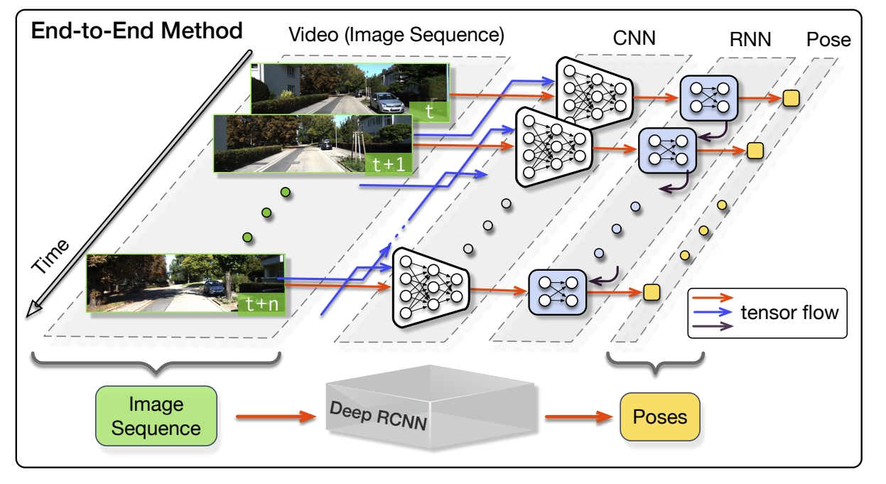
The framework of the proposed method. RCNN takes a sequence of RGB images (video) as input and learns features by CNN for RNN based sequential modelling to estimate poses.
DeepEvent-VO use the same framework.It is composed of CNN for geometric feature extraction and RNN for sequential learning (modelling the dynamics and relations among a sequence of CNN features).
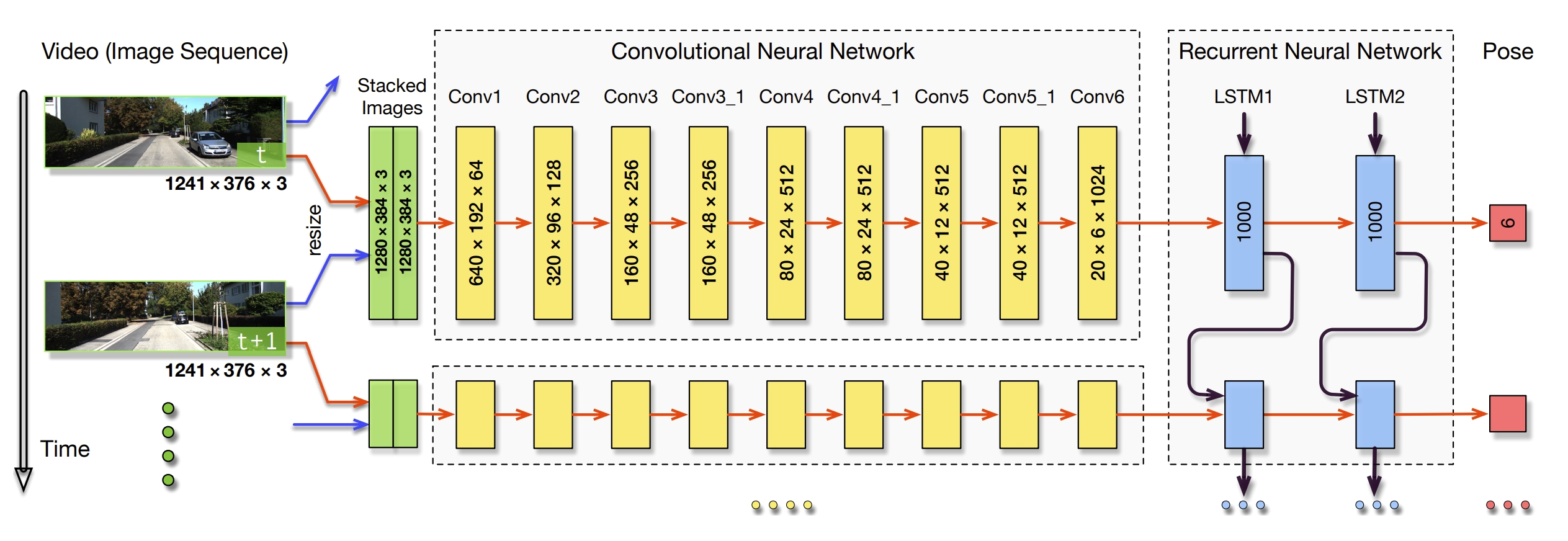
-
It seems that the geometric feature extraction is just a manual explanation, since the network doesn't have any supervise label for this geometric feature, how to ensure the CNN network learn the geometric feature.
-
Cost Function
The input is the RGB image while the target is the pose of the camera. The pose is represented by the 6-DOF transformation matrix. The cost function is the Mean Square Error (MSE) between the predicted pose (positions and orientations) and the ground truth pose.
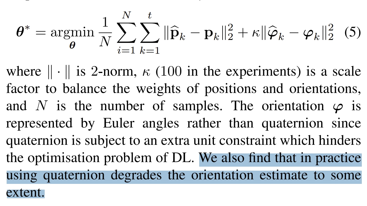
- only done on the KITTI dataset.
- worse than the traditional methods.
UnDeepVO: Monocular Visual Odometry through Unsupervised Deep Learning
ICRA2018Contributions:
- estimate the 6-DoF pose of a monocular camera and the depth of its view (both tracking and mapping).
- unsupervised scheme: train with unlabeled datasets and can be applied to localization scenarios (through the spatial and temporal geometric constraint).
- absolute scale recovery for both pose and dense depth: train UnDeepVO by using stereo image pairs to recover the scale but test it by using consecutive monocular images.
- stereo image training without the need of labeled datasets.
Since rotation (represented by Euler angles) has high nonlinearity, it is usually difficult to train compared with translation. For supervised training, a popular solution is to give a bigger weight to the rotational loss as a way of normalization.
The pose estimator is a CNN architecture.
In order to better train the rotation with unsupervised learning, the authors decouple the translation and the rotation with two separate groups of fully-connected layers after the last convolution layer. This enables the network to introduce a weight normalizing the rotation and the translation predictions for better performance.The depth estimator is an encoder-decoder architecture.
Instead of produce the disparity images, it directly predicts the depth maps.
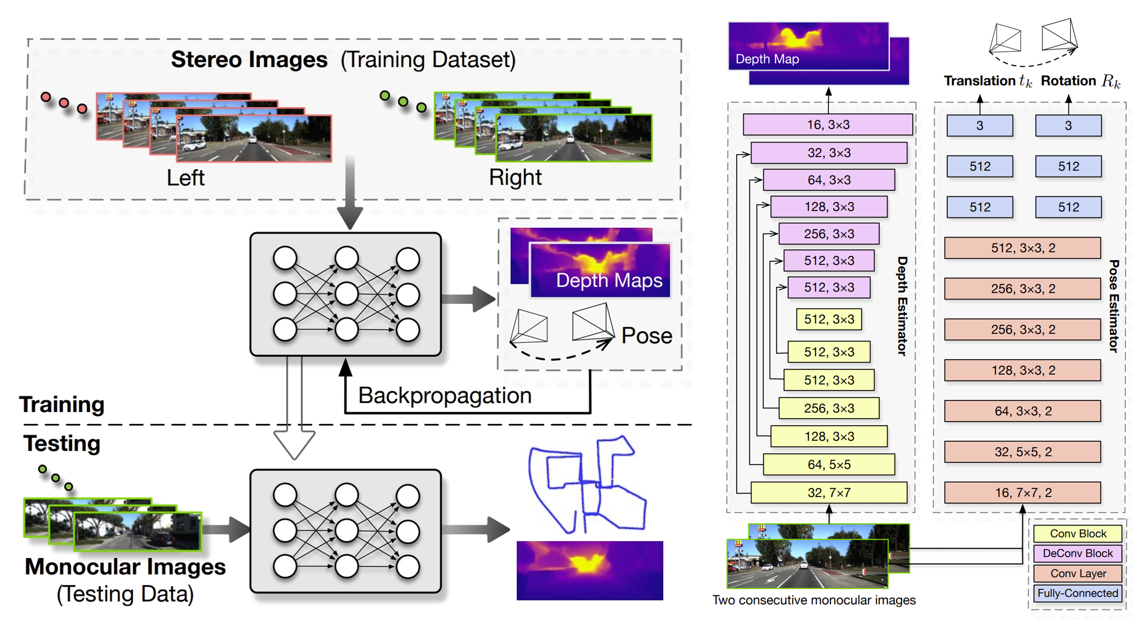
After training with unlabeled stereo images, UnDeepVO can simultaneously perform visual odometry and depth estimation with monocular images. The estimated 6-DoF poses and depth maps are both scaled without the need for scale postprocessing.
Its total loss includes spatial image losses and temporal image losses.
The spatial image losses drive the network to recover scaled depth maps by using stereo image pairs,
while the temporal image losses are designed to minimize the errors on camera motion by using two consecutive monocular images.
As shown in following Figure, utilizing both spatial and temporal geometric consistencies of a stereo image sequence to formulate the loss function.
The red points in one image all have the corresponding ones in another.
Spatial geometric consistency represents the geometric projective constraint between the corresponding points in left-right image pairs, while temporal geometric consistency represents the geometric projective constraint between the corresponding points in two consecutive monocular images (🤔similar to the re-projection or BA?)
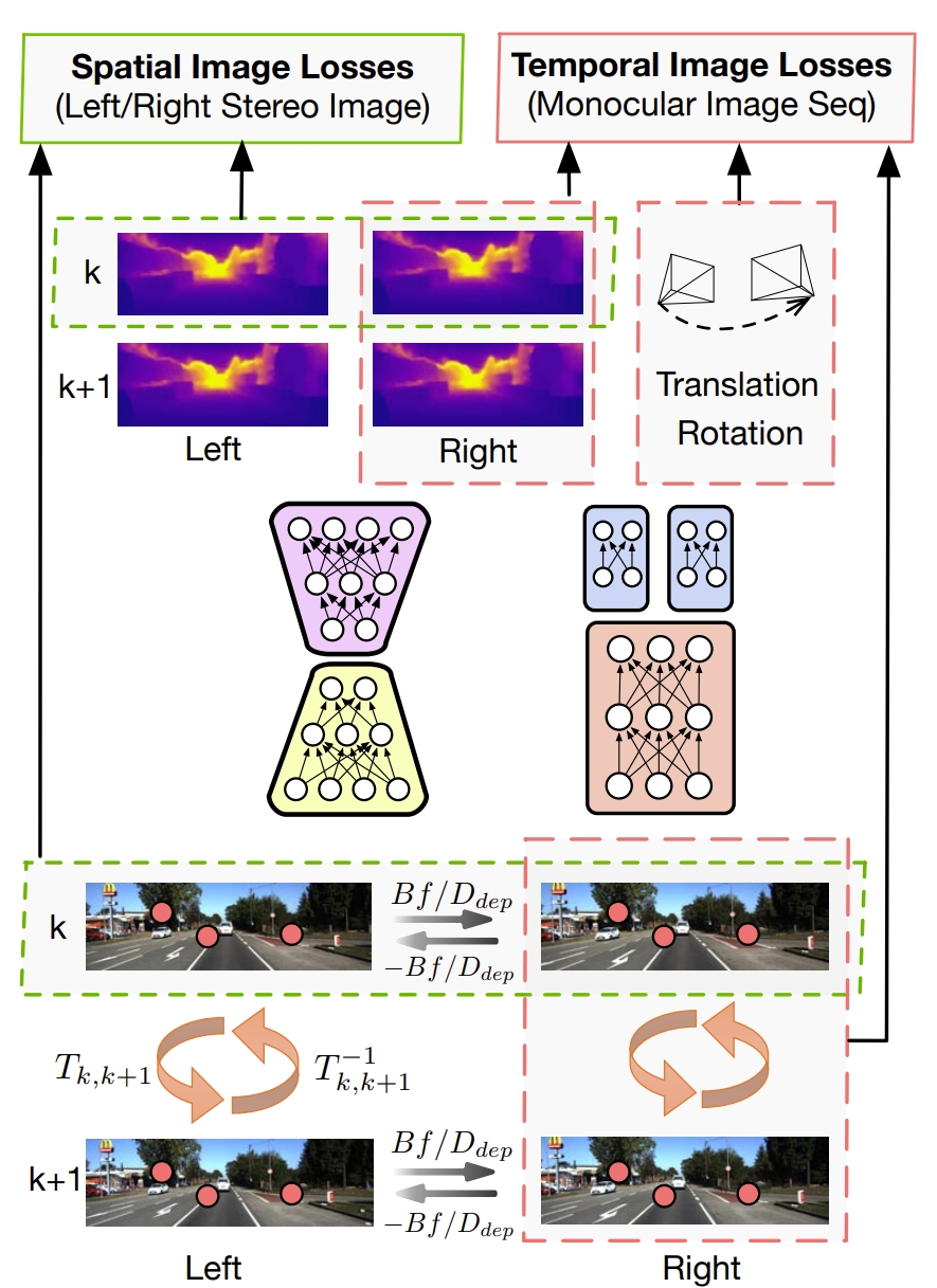
Training scheme of UnDeepVO. The pose and depth estimators take stereo images as inputs to estimate 6-DoF poses and depth maps, respectively. The total loss including spatial losses and temporal losses can then be calculated based on raw RGB images, estimated depth maps and poses.
Spatial Image Losses, including the left-right photometric consistency loss, disparity consistency loss and pose consistency loss.
(i) Photometric Consistency Loss:- Assume pL(uL, vL) is a pixel in the left image and pR(uR, vR) is its corresponding pixel in the right image. Then, we have the spatial constraint uL = uR and vl = vR +DP.
- using the following figure, we can calculate the horizontal distance between the stereo images using the depth value of the network
- using the previous horizontal distance map DP, we can synthesize one image from the other through “spatial transformer”. And then the combination of an L1 norm and an SSIM term is used to construct the left-right photometric consistency loss:
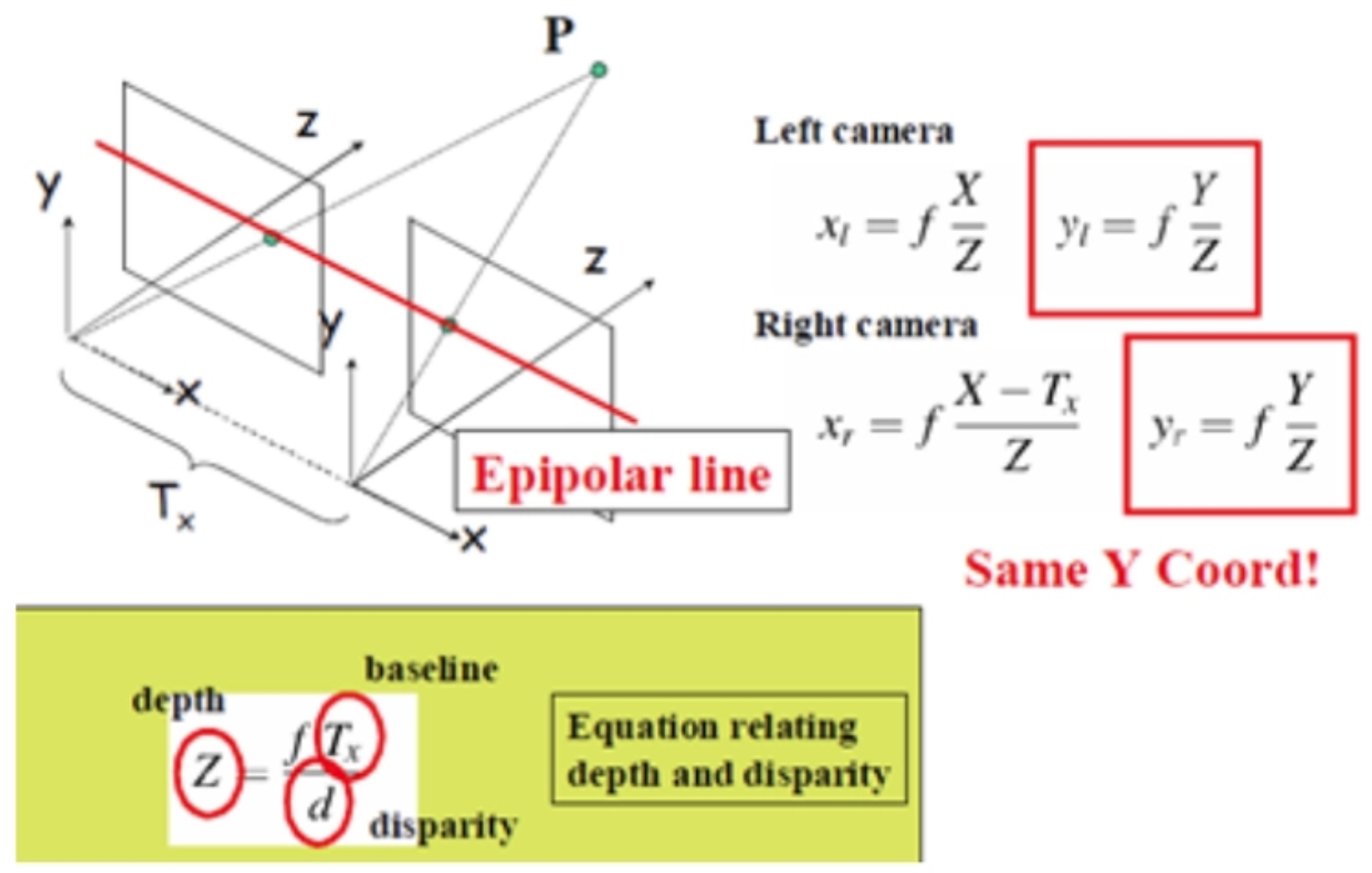
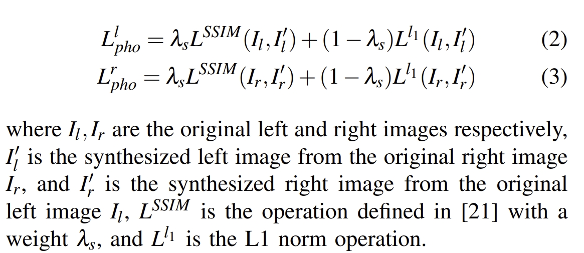
Through the horizontal distance map DP, we can calculate the disparity map.
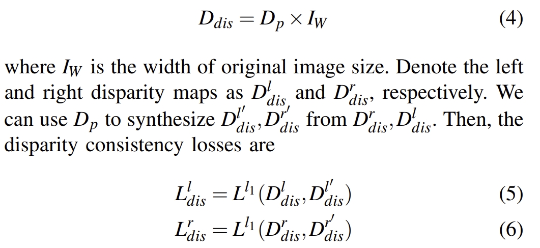
The depth map is generated from the network. The horizontal distance map DP is calculated from the depth map. Through the horizontal distance map DP, we can calculate the disparity map. AKA. the disparity map can be obtained from the depth map of the network. While the disparity map of left and right images should be consistent. (I think the description in the original paper is not clear enough, this is my understanding)
both left and right images are taken from the same camera, the transformations between the left and right images should be basically identical.

Temporal Image Losses, including photometric consistency loss and 3D geometric registration loss.
(i) Photometric Consistency Loss:Align the k and k+1 frames based on the predicted relative pose, camera internal parameters, and predicted depth map. For two consecutive frames, the photometric should be very similar.
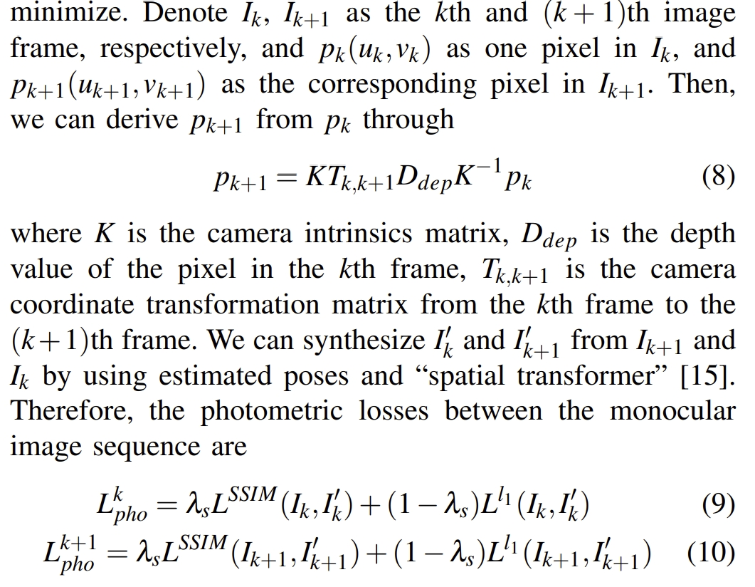
similar to the ICP, the point cloud of the k frame can be transformed to the k+1 frame through the estimated transform. Then minimize the loss between the transformed point cloud and the estimated point cloud of the k+1 frame in the network.
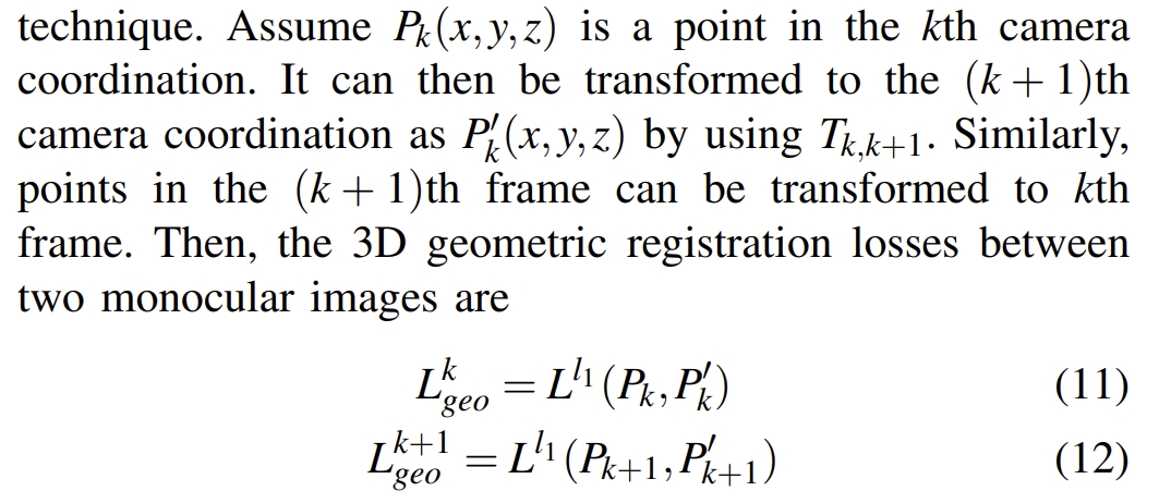
🙋In my opinion, all the above-mentioned loss is very similar to the concept of the re-projection error in the traditional VO pipeline. Or, in other words, it is very similar to the Bundle Adjustment. The created loss should be minimized (ideally case is zero) to obtain the optimal pose and depth map.
Experiments:better than ORB-SLAM2 in KITTI dataset.
Recurrent neural network for (un-) supervised learning of monocular video visual odometry and depth
CVPR2019Contributions:
convolutional Long Short-Term Memory (ConvLSTM) units: to carry temporal information from previous views into the current frame’s depth and visual odometry estimation. Since it utilizes multiple views, the image reprojection constraint between multiple views can be incorporated into the loss (rather than only two consecutive frames), therefore it has performance improvement.
More details about the multi-view re-projectioin constraint can be found in the paper.forward-backward flow-consistency constraint (idea is from the GeoNet): provides additional supervision to image areas and improves the robustness and generalization ability of the model.
It works as self-supervision and regularization. Through some strategies, we can get the dense flow field from k to k+1, while the dense flow field in k+1 can be estimated from the network. Therefore, minimize these two flow fields can provide additional supervision.
CVPR2018
Contributions:
Jointly learning three components: depth, optical flow, and camera pose (VO), using divide-and-conquer strategy.
Most of the natural scenes are comprised of rigid static surfaces. Their projected 2D image motion between video frames can be fully determined by the depth structure and camera motion. Meanwhile, dynamic objects commonly exist in such scenes and usually possess the characteristics of large displacement and disarrangementgeometric consistency loss through forward-backward (or left-right) consistency check.
This is based on the assumptions of photo consistency as well as the geometric consistency between the two consecutive frames.Concept of dynamic VO: The 2D projection image of a static background between image frames is entirely determined by depth structure and camera motion, and can be simulated using optical flow to capture camera motion. While the motion of a dynamic target is determined by both camera motion and its own motion
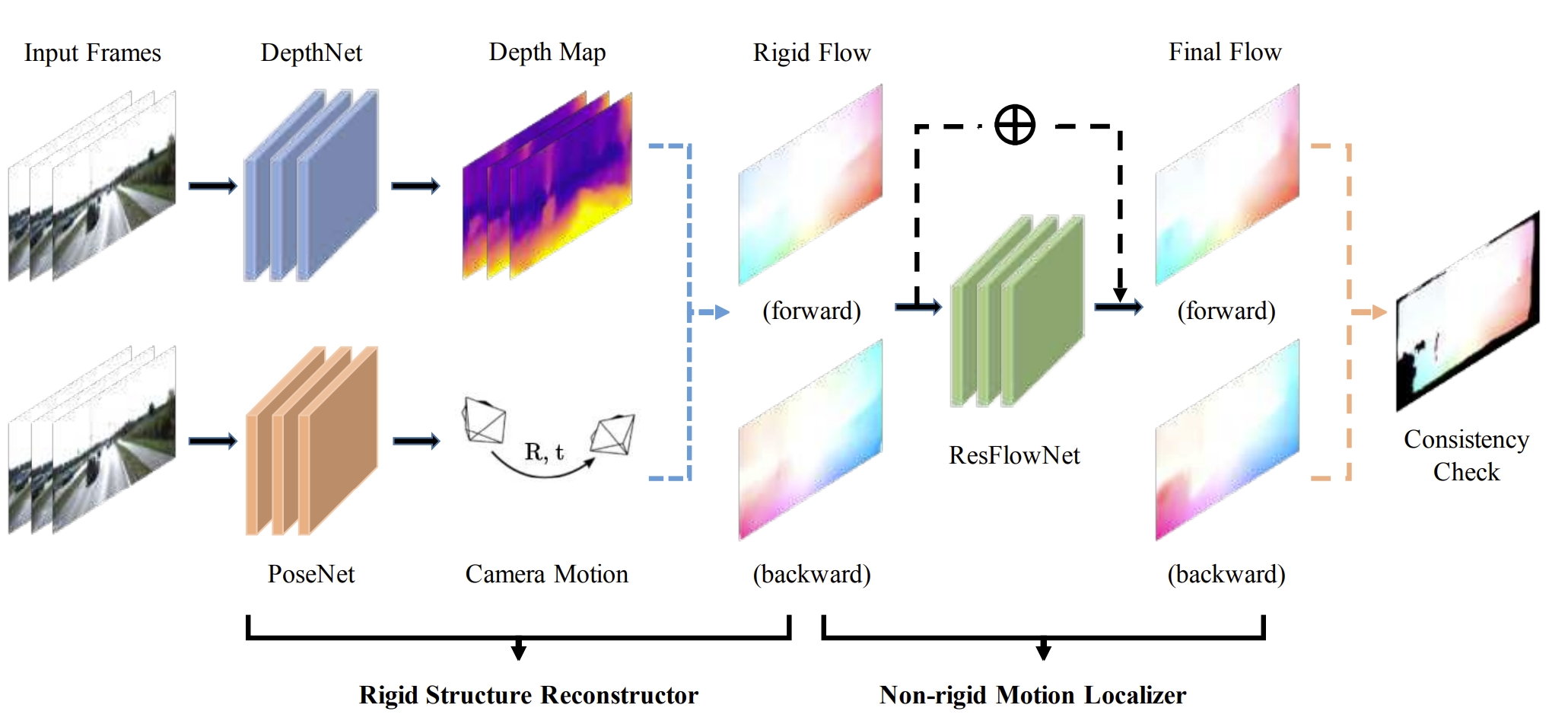
Methodology:
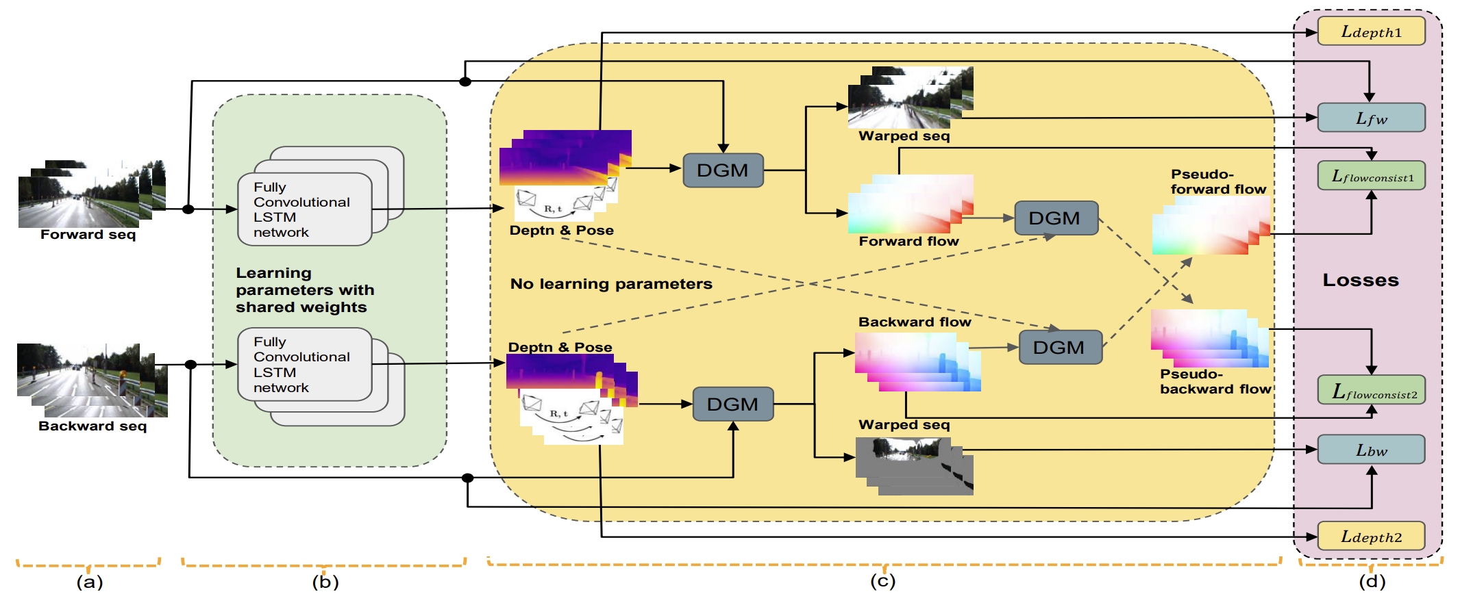
Training scheme of the proposed method.
Note that: with depth as input target, the network can estimate the depth at absolute scale, otherwise, the depth is only at relative scale.
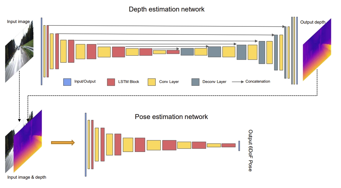
Network architecture of the proposed method. Very similar to the UnDeepVO, but with the ConvLSTM.
DROID-SLAM: Deep Visual SLAM for Monocular,Stereo, and RGB-D Cameras
NIPS2021In the perspective of mapping, DROID-SLAM employs a "stitched predictive optical flow + DBA + Upsample" approach, it significantly enhances the generalization of a pre-trained model across various scenarios compared to the existing depth estimation networks.
In the perspective of pose tracking, different from feature-based SLAM methods, DROID-SLAM fully utilizes 1/8 down-sampled RGB information and predicts optical flow using a pre-trained model, this eliminates the need for feature matching. On the other hand, compared to direct SLAM, the optical flow prediction module of the DROID-SLAM supports global BA, whereas direct-based methods cannot perform global BA between two frames that are far away from each other.
Truly realize high accuracy pose estimation and based on their previous work RAFT(for optical flow tracking).
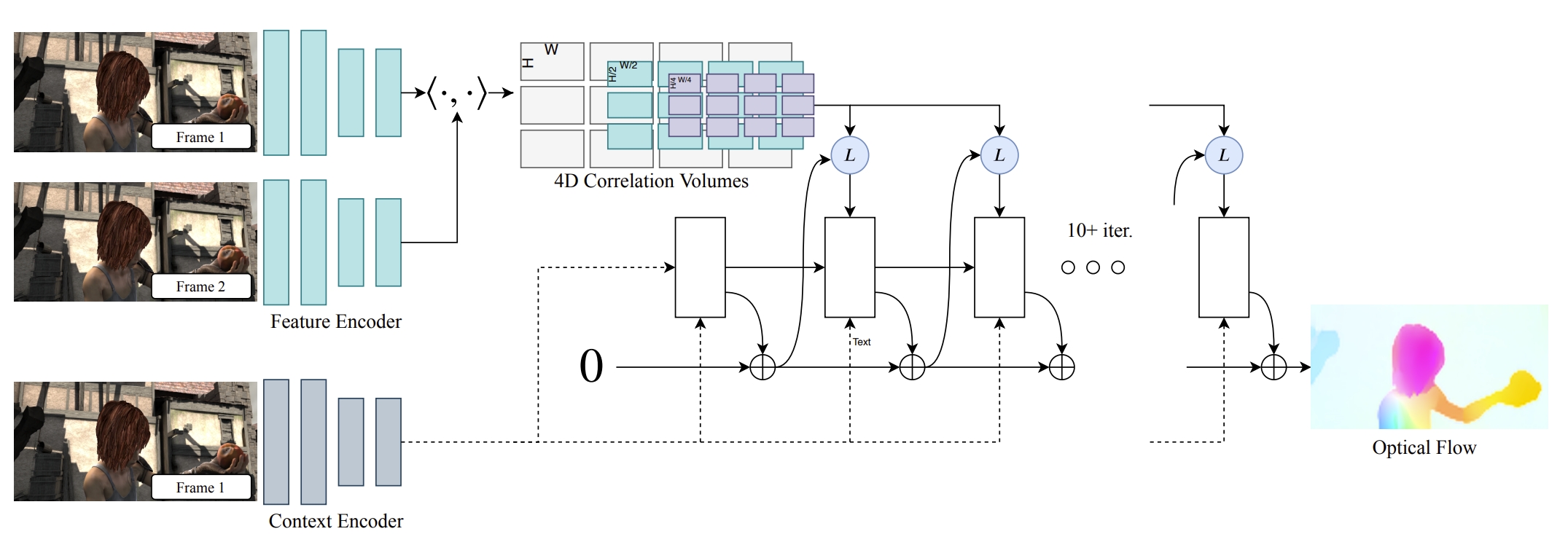
The feature extraction: is borrowed from the RAFT, which is composed of two separate networks: a feature network and a context network. T The feature network is used to build the set of correlation volumes, while the context features are feed into the network during each application of the update operator.
The update operator: recurrent iterative updates, building on the RAFT, iteratively update the camera poses and depth. While each update is produced by differentiable dense bundle adjustment (DBA) layer.
- Dense Bundle Adjustment Layer (DBA): create the loss between the projected points and the predicted point of the update operator
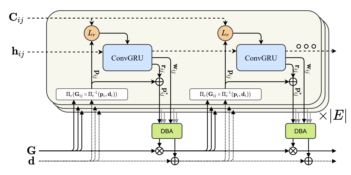

- high robustness and good generalization ability: EuRoC, TUM-RGND, TartanAir, ETH-3D
- outperform the ORB-SLAM3 in EuRoC using monocular or stereo input .
Tartanvo: A generalizable learning-based vo
CoRL2021Contributions:
-
Pose the question: why haven’t we seen the deep learning models outperform geometry-based methods yet?
The first reason is the diversity of the training data. The motivation to solve this problem is based on the "common sense": a large number of studies show that training purely in simulation but with broad diversity, the model learned can be easily transferred to the real world.
The second reason is that most of the learning-based method ignore some fundamental nature of the problem which is well formulated in geometry-based VO theories. For example, the scale ambiguity, take the intrinsic parameters into consideration, etc. Only. using TartanAir data for training, so that: generalizes to multiple datasets and real-world scenarios (e.g. EuRoC, KITTI), outperforms the geometry-based methods in challenging scenarios.


Diffposenet: Direct differentiable camera pose estimation
CVPR2022Motivations:
For the classical approaches, they use structure from motion estimate 3D motion utilizing optical flow and then compute depth. Therefore, the pose estimation is dependent on the scene structure.
While the direct-based methods separate 3D motion from depth estimation, but compute 3D motion using only image gradients in the form of normal flow.all the optical flow algorithms have large errors in regions of non-uniform gradient distributions. This should be common sense since the assumptions of the optical flow is the brightness constancy and the motion smoothness (should be equal to the gradient constancy).
Therefore, this paper design a network for normal flow estimation (create the direct constraints). Through the differentiable optimization layer to estimate the camera pose from the normal flow. What's more, it also highlights the robustness and cross-dataset generalizability without any fine-tuning or re-training.
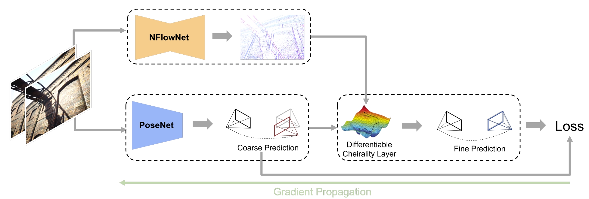
The NFlowNet and the PoseNet are trained firstly. Then the whole network is trained in self-supervision fashion via the refinement loss.
Deep patch visual odometry
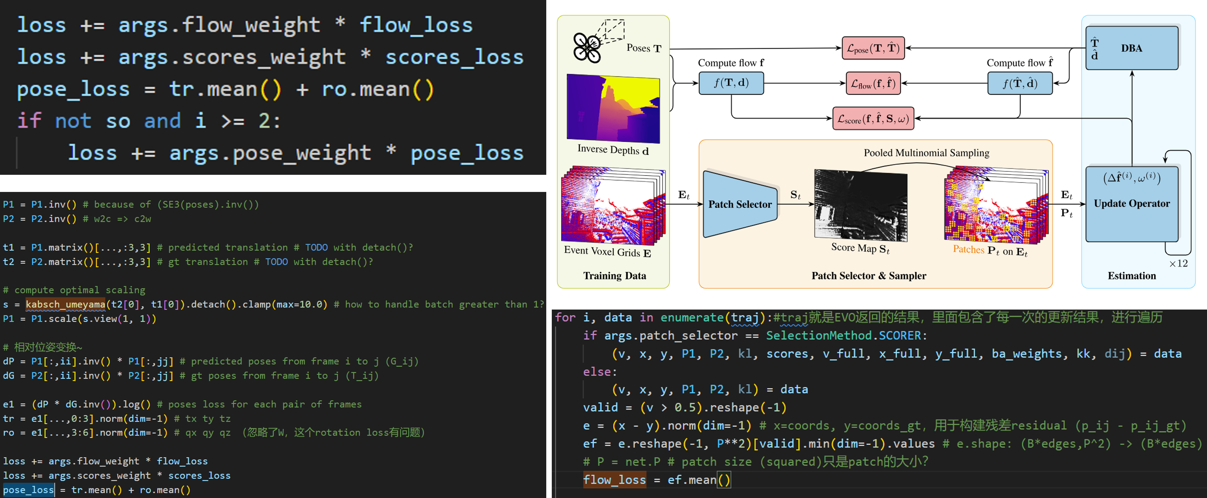
NIPS2024An extension of DROID-SLAM through using sparse VO, which achieves similar accuracy but much lower cost. 😊There are some event-based works developed based on the DPVO:
3DV2024
Comment and evaluation of the DEVO
Package the event data into voxel-based representation, and design a patch selector for the event data. While the other part is same as the DPVO.
Learning-based VIO
The above mentioned methods are learning-based VO that use only the visual information. It is wellknown that including an additional inertial measurement unit (IMU) can enhance the robustness of visual SLAM methods. What's more, the IMU can estimate the absolute scale of the motion, it is easier to estimate the up-to-scale pose.
Vinet: Visual-inertial odometry as a sequence-to-sequence learning problem
AAAI2017
Github Link Contributions:
The first end-to-end trainable VIO.
It eliminates the need for manual synchronization as well as calibration between the IMU and camera.
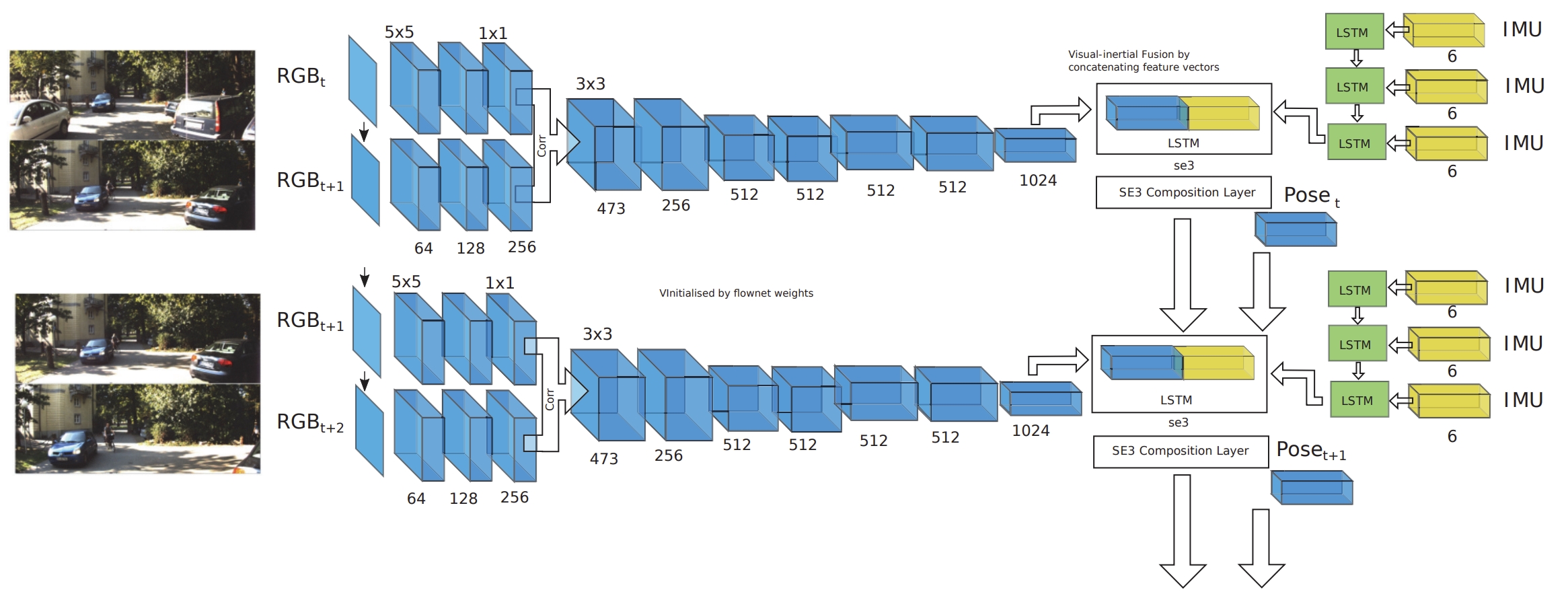
LSTM processing the pose output at camera-rate and an IMU LSTM processing data at the IMU rate.
Deepvio: Self-supervised deep learning of monocular visual inertial odometry using 3d geometric constraints
IROS2019
Motivations:
The direct-based representative DSO and the feature-based representative ORB-SLAM both achieve very high localization accuracy in the large-scale environment, and real-time performance with commercial CPUs.
However, they still face some challenging issues when they are deployed in non-textured environments, serious image blur or under extreme lighting conditions.
VIO are proposed to eliminate these limitations.
However, the current VIO systems heavily rely on manual interference to analyze failure cases and refine localization results. Furthermore, all these VIO systems require careful parameter tuning procedures for the specific environment they have to work in.
Compared to the traditional methods, DeepVIO reduces the impacts of inaccurate CameraIMU calibrations, unsynchronized and missing data.
Merging 2D optical flow feature and the IMU data.
2D optical flow network is constrained by the projection of its corresponding 3D optical flow. While the 3D optical flow is obtained through estimating the depth and dense 3D point cloud of each scene by using stereo sequences.
The IMU data is feed to the LSTM-style IMU pre-integration network.
The network is composed of CNN-Flow, LSTM-IMU, and FC-fusion network.
CNN-Flow: estimated the 2D optical flow.
LSTM-IMU: works as IMU pre-integration network to calculate the relative 6-DoF pose between adjacent two frames. (The LSTM network is usually difficult to coverage because of the noises and changes of IMU data).
FC-Fusion network: calculate the final pose.

Bamf-slam: bundle adjusted multi-fisheye visual-inertial slam using recurrent field transforms
ICRA2023Contributions:
DROID-SLAM+IMU: utilizes Bundle Adjustment (BA) and recurrent field transforms (RFT) to achieve accurate and robust state estimation.
minimize the re-projection errors of dense depth maps using the prediction of RFT as targets (DROID-SLAM and RAFT).using the fisheye images, integration of multi-camera inputs.
loop closure: the wide FoV of the fisheye camera allows the system to find more potential loop closures, and powered by the broad convergence basin of RFT, it can perform very wide loop closing with little overlap.
Proposed semi-pose-graph BA method to avoid the expensive full global BA.
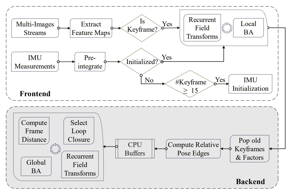
Despite only being trained on the TartanAir dataset of pinhole images, the pre-trained model by DROID-SLAM has excellent generalization ability on fisheye images. Therefore, the author use the pre-trained model without further fine-tuning.
- The IMU initialization is adopted from ORB-SLAM3.
- marginalization is not considered.
DVI-SLAM: A dual visual inertial SLAM network
Contributions:
integrate both photometric factor and re-projection factor into the end-to-end differentiable structure through multi-factor data association module. (feature-based + direct-based)
- The output is camera pose (rotation and translation), depth map, and IMU motion (velocity, ba, bg).
feature-metric factor (served as the direct-based method?).
Using the feature extraction model of DROID-SLAM to extract the correlation features (for estimate the dense flow map), this acts as feature-based method.
add a U-Net structure to extract the appearance feature, this acts as direct-based method.
build upon DROID-SLAM, it consists of two modules and one layer: (a) a feature extraction module, (b) a multi-factor data association module, and (c) a multi-factor DBA layer.
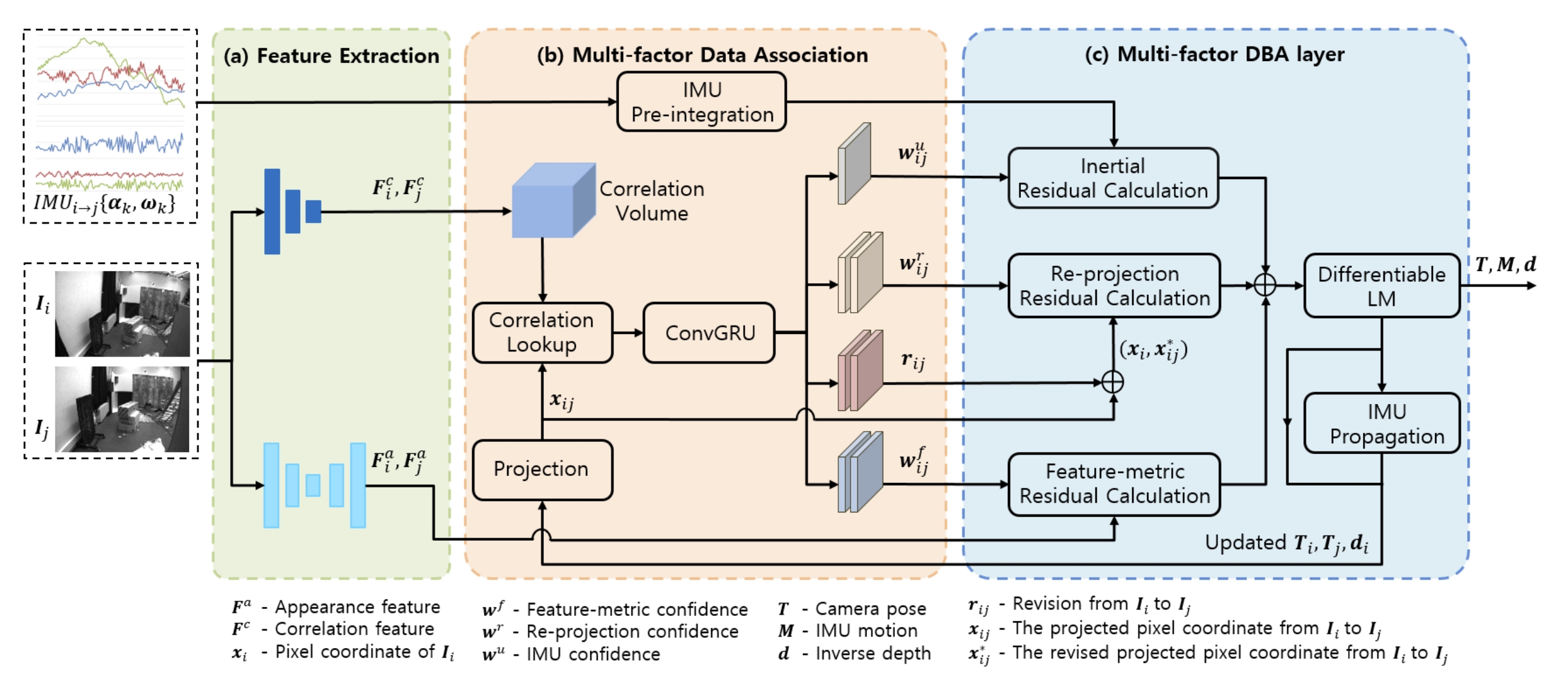
the re-projection factor dominates at the early stage of BA optimization to get a good initialization and avoid getting stuck in local minima. In the later stage, both the feature-metric factor and re-projection factor smoothly steer the joint optimization towards a true minimum. The network also dynamically adjusts the confidence map of IMU factor.


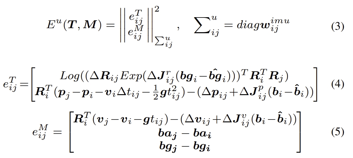

(i) The pose loss is the distance between ground truth pose and the predicted pose,
(ii) The low flow loss is the distance between the predicted flow and GT flow which is converted from GT pose and depth.
(iii) Re-projection loss and feature-metric loss are the distances of the re-projection error and feature-metric error.
The network is required to be trained in three state with supervision of the pose, GT flow.

Firstly, multiple keyframes are collected to build a frame graph, and camera pose and inverse depth states are optimized by DBA layer.
Then initialize the gravity direction and IMU motion according to the estimated camera pose and IMU pre-integration result. For the monocular visual and inertial streams, the absolute scale is also initialized.
Finally, minimize re-projection residual, feature-metric residual, and inertial residual with DBA layer to refine camera pose, motion, and inverse depth.
DBA-Fusion: Tightly Integrating Deep Dense Visual Bundle Adjustment with Multiple Sensors for Large-Scale Localization and Mapping
RAL2024
Github Link
Motivations:
Fusing learning-based methods with multi-sensor information.
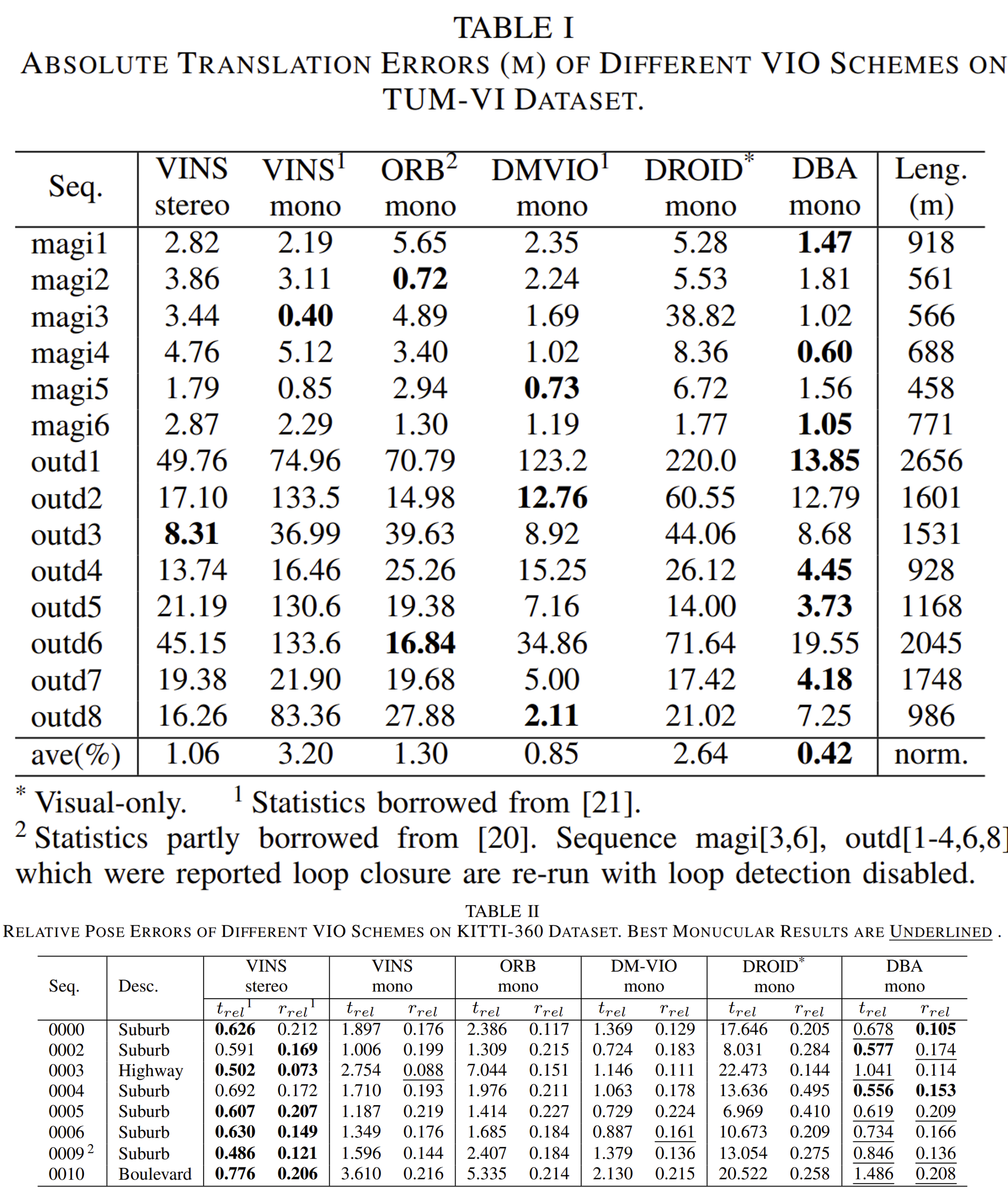
This work proposed the generic factor graph framework to tightly integrate the trainable deep dense bundle adjustment (DBA) with multi-sensor information through a factor graph.
The Hessian information derived from DBA is fed into a generic factor graph for multi-sensor fusion, which employs a sliding window and supports probabilistic marginalization.
for enhancing the learning-based visual SLAM through multi-sensor fusion.Flexibly fuses a trainable visual SLAM with multi-sensor information (e.g. IMU, wheel odometry, GPS, etc.).

More details of the code-comment and the testing can be seen in Link.
The visual-inertial initialization is same as DVI-SLAM (also adopted from VINS-Mono).
For the learning-based visual process, aka. the recurrent optical flow is from the network which is pre-trained in the DROID-SLAM.
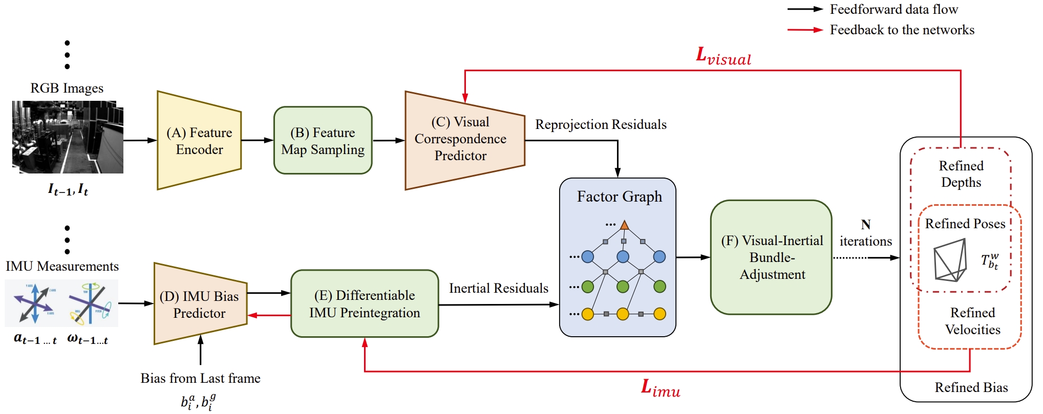
Adaptive VIO: Deep Visual-Inertial Odometry with Online Continual Learning
Motivations:
1. Traditional VIO is less robustness, which can be attributed to the reliance on low-level and hand-crafted visual features.
2. trajectory drift caused by IMU bias is also one of the critical reasons affecting the system’s performance, while traditionally modeling IMU bias as a random walk is insufficient to reflect its evolutionary patterns.
Key-points: using two networks to predict visual correspondences and IMU bias , respectively.
Combining deep learning with the visual-inertial bundle adjustment.
Frameworks of different VIO methods:
- (a) Classic optimization-based method.
- (b)End-to-end learning-based method.
- (c) Learning-optimization-combined method with online continual learning.
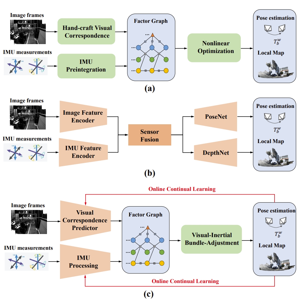
- The pipeline of the method
- The feature encoder and visual correspondence predictor adopt similar network structures to DPVO, but without the hidden state.
- The online continual learning is proposed to handle the performance degradation in unseen environment.
- The visual network requires pre-training, while the IMU bias network does not. (since it has the online continual learning).
