Sensors Synchronization for Event Camera
1. Abstract
In this report, we will provide a brief overview of our sensor synchronization process. This primarily involves synchronizing event cameras, synchronizing different types of sensors, and synchronizing onboard computers across multiple platforms.
😀For the details of Event Cameras calibration, please refer to:
- Achieving image reconstruction from event streams, and then using the Kalibr toolbox for camera-and-IMU calibration: Link
- Using dv-gui for camera-and-IMU calibration: Link
- Assuming that the event camera is consistent with the image camera in pixel coordination, use the Kalibr toolbox to calibrate the image sensor: Link
2. The Synchronization of Event Cameras
The event camera has an additional synchronization interface, called as "sync connectors", as shown in the figure below. (Using DAVIS346 as example reference to Link, same as DVXplorer Link).
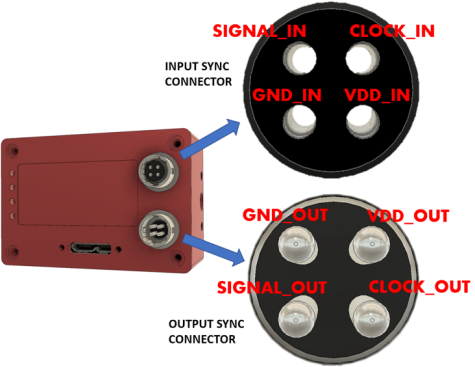
The synchronization connectors are HiRose HR10A-7R-4P (male, SYNC OUTPUT) and HR10A-7R-4S (female, SYNC INPUT) connectors. Cables should use the matching connectors HR10A-7P-4S (female) and HR10A-7P-4P (male). Please note that to keep full electrical isolation between different cameras, the cable should not be shielded, or if it is, the shield should not connect one end of the cable to the other. Input signals can be 3.3V or 5V, depending on the VDD_IN supplied externally, output signals are 5V, as is VDD_OUT. If you chain cameras together for synchronization, the clock and VDD will be 5V, for example.
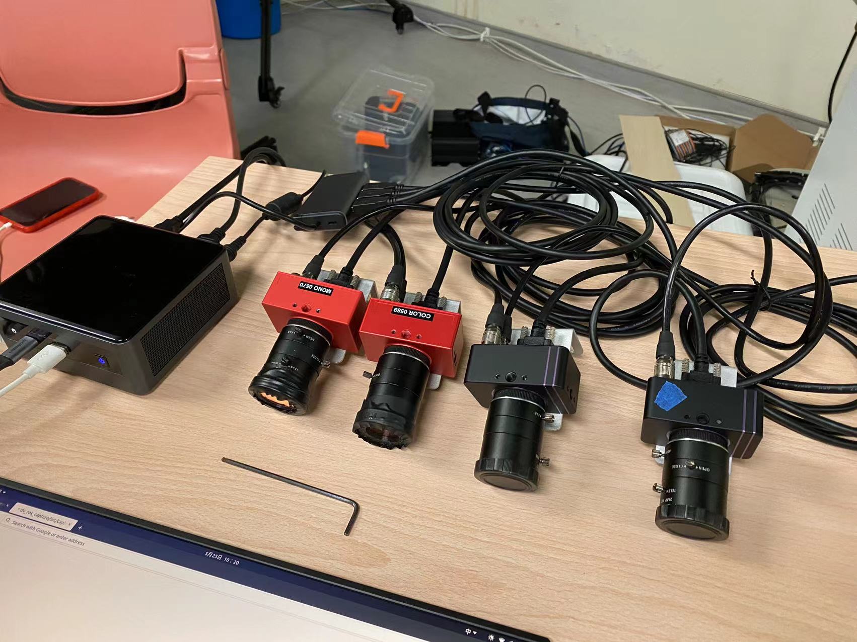
Therefore, utilizing this sync connector, we connected four event cameras together (two DAVIS346 and two DVXplorer) as shown in the diagram below. Additionally, we replaced the event camera ROS driver Code provided by Invitation Company with our own driver Code.
There are two key parameter in the driver code of event camera for synchronization, syncDevices and waitForSync
<rosparam param="syncDevices">["series number of your event camera"]</rosparam>
A list of other cameras connected with synchronization cable to this camera, If this list is empty, the camera node will not properly synchronize them.
<param name="waitForSync" value="true"/>
This means that it does not publish data until synchronization is complete. The launch file of our event camera synchronization can be seen in Link. We use an event camera as "master" while the other three event cameras is waiting on list. Through the series number of the event camera to avoid mis-match.
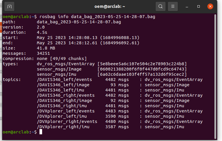
Furthermore, to validate the synchronization effect, we simultaneously started four event cameras, recorded a rosbag, and then outputted the rostopic, as shown in the figure below. It can be observed that "/DAVIS346 left/events: 4482", "/DAVIS346 right/events: 4482", "/DVXplorer left/events: 4483", and "/DVXplorer right/events: 4480". The data volume from all four event cameras is similar. Additionally, from the video demo, it can be seen that when the event cameras are started, there is a waiting period until all of them have finished initializing. Moreover, the difference in data volume between "/DAVIS346 left/events" and "/DAVIS346 left/imu" is only 1, and both are recorded at 1000Hz.
3. The Synchronization of Multi Sensors
3.1. The Synchronization of Two Onboard Computer
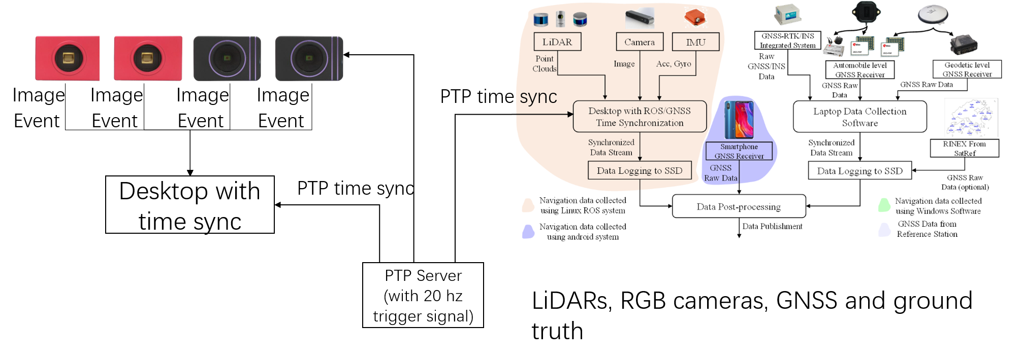
Firstly, we install the PTP.
sudo apt install ptpd
Choose a machine to serve as the master node and initiate the following on it (where eth0 is the selected network interface for synchronization, please note that it requires the connected switch to support the PTP protocol):
sudo ptpd -M -i eth0
On the remaining slave nodes, initiate the following:
sudo ptpd -g -i eth0
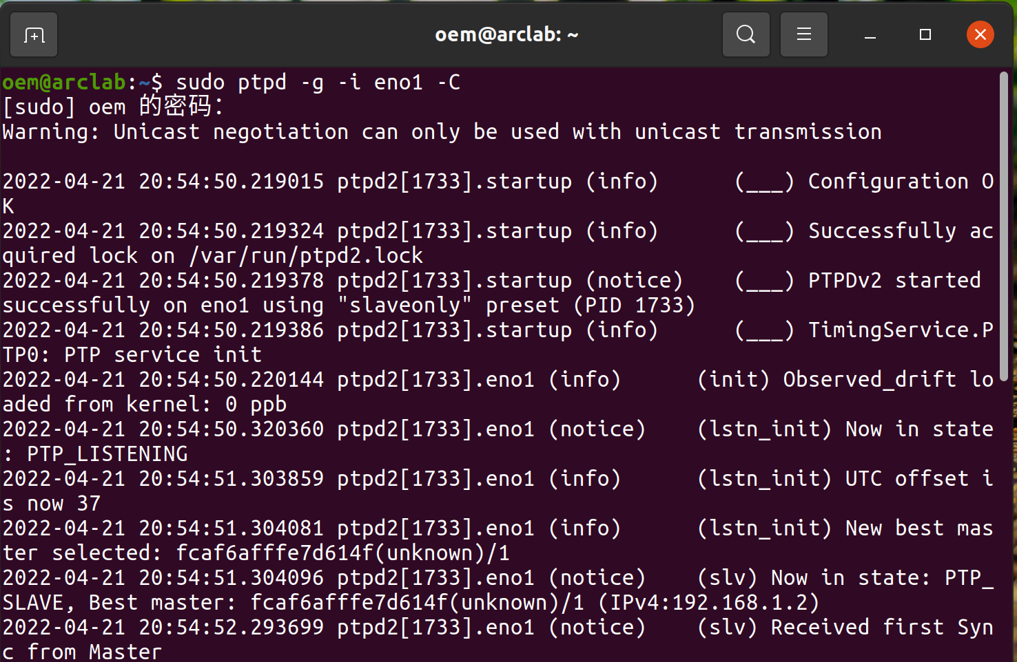
If the "-C" parameter is added to both the master and slave, it will run in the foreground and print the output. For example, on the master side:
sudo ptpd -g -i eth0 -C
3.2 The Synchronization of Event Camera and Standard Camera
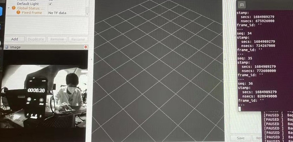
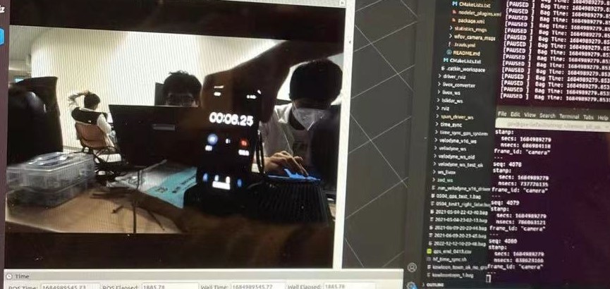
After synchronizing the clock cycles between two onboard computers, we set the image publishing frequency of DAVIS346 on onboard computer A to 20Hz, and the publishing frequency of the industrial camera on onboard computer B to 20Hz as well. Then, we placed a stopwatch in front of both cameras. We observed the stopwatch values for image topics with the same timestamps from both cameras. After multiple verifications, we concluded that the time difference between the DAVIS346 on onboard computer A and the industrial camera on onboard computer B, directly capturing images, was within 10ms, which aligns with our expectations.
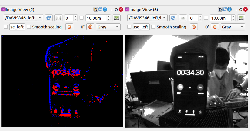
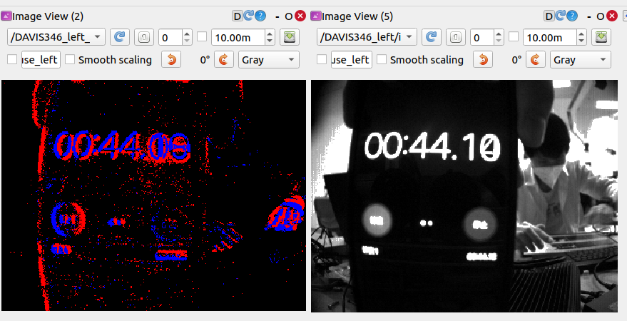
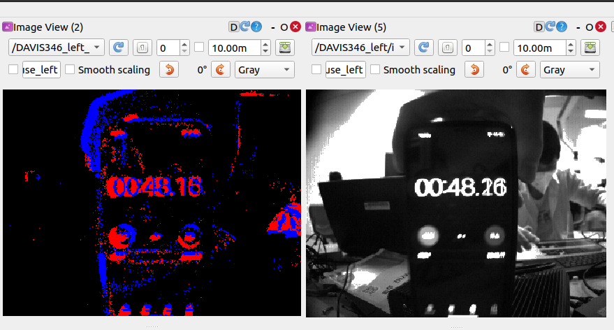
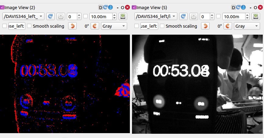
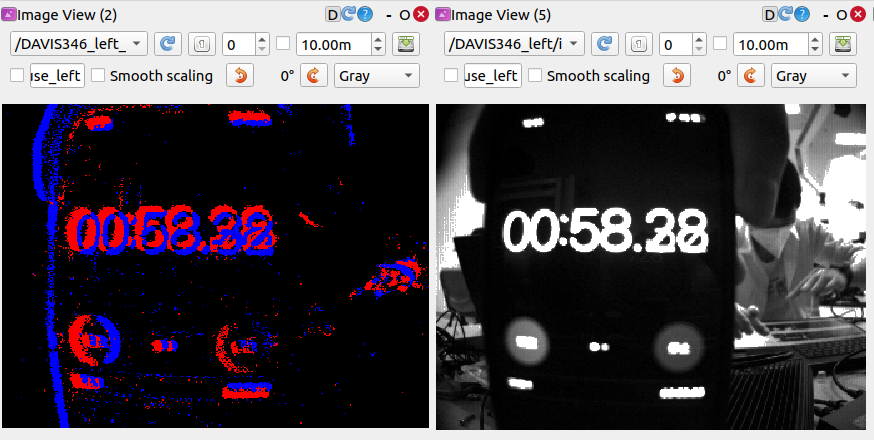
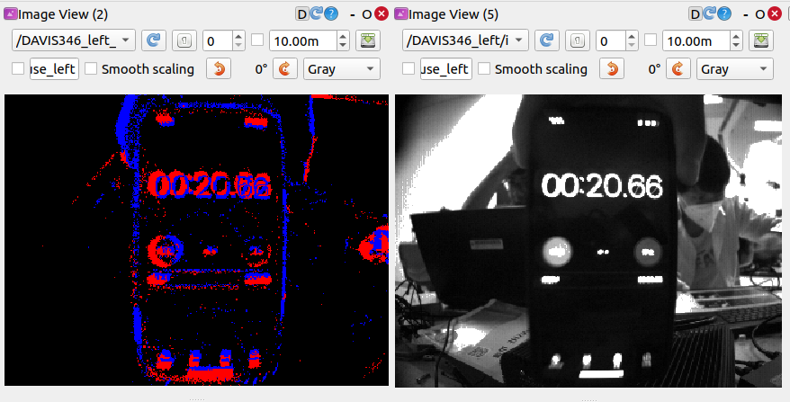
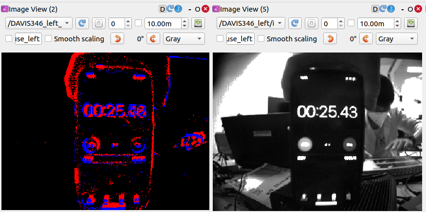
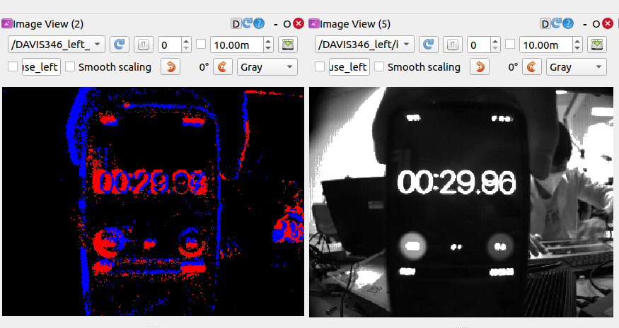
We further test the synchronization between the event and image data streams in DAVIS346 as following:
3.3. The Synchronization of Other Sensors
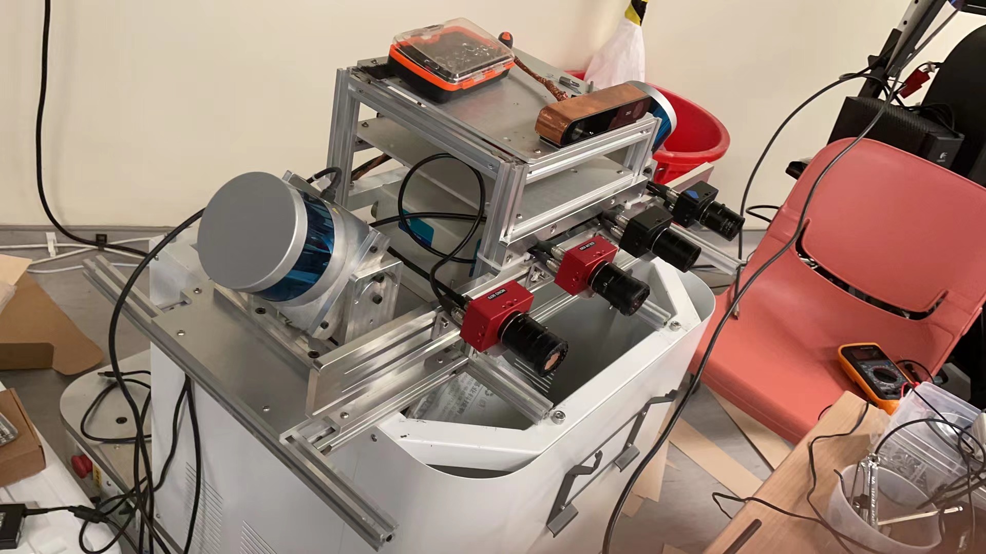
Our sensor platform can be seen as following:
Tips:
-
Event cameras are sensitive to infrared light, enabling them to detect the brightness changes caused by LiDAR with the right wavelength.
To alleviate disturbance from the LiDAR on the event camera, we add an infrared filter on the lens surface of the DAVIS346 camera. As can be seen from the video, we demonstrate that two event cameras with infrared filter while the other two event cameras without infrared filter.